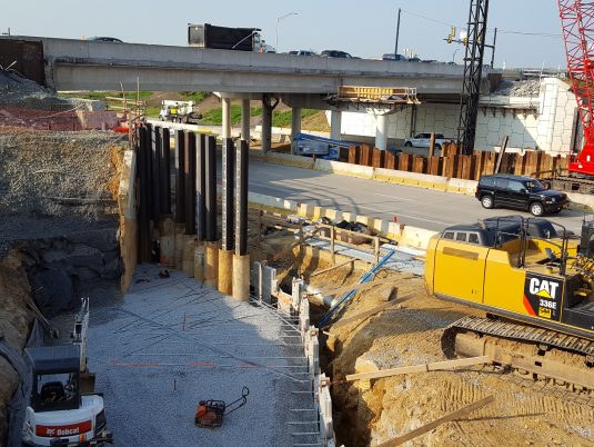
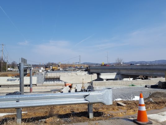
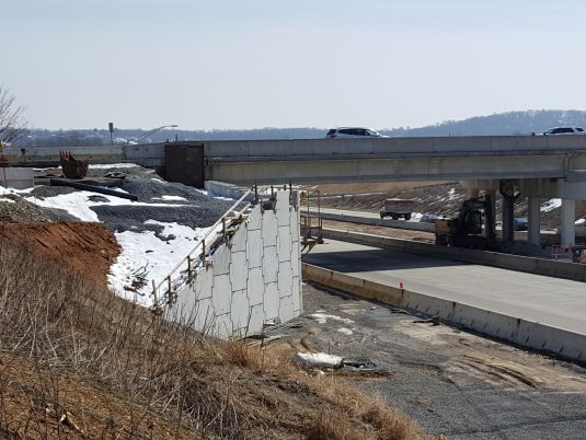
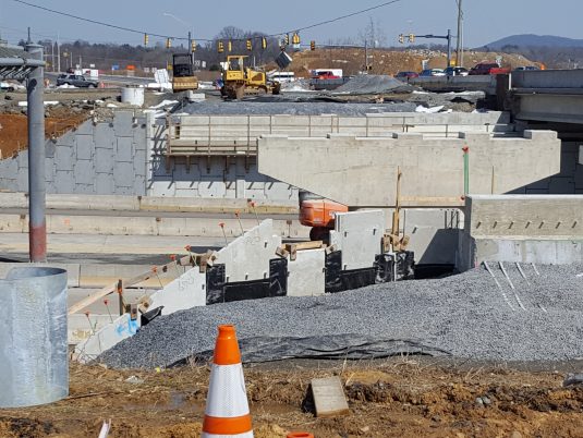


Completed in 2017, this project involved the widening of the Freemansburg Avenue bridge over SR 33, using a partially shored mechanically stabilized earth retaining wall. The existing structure was a double-span bridge with abutments on either end. The abutments sat on piles to carry the vertical and lateral loads from the bridge. Each abutment was built with a mechanically stabilized earth (MSE) wall in front, and flared MSE wing walls.
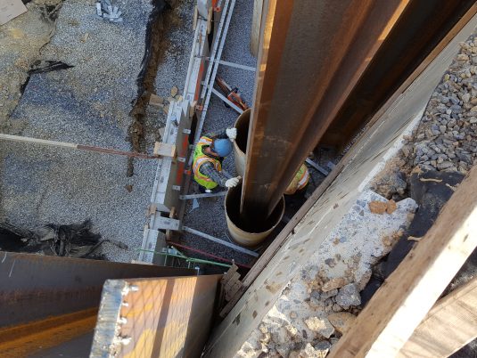
The proposed widening involved extending the bridge abutment seat in one direction by driving new piles to align with the existing, then building a new MSE abutment wall and wing wall to interface with the existing wall.
A design problem arose when determining how to continue the abutment seat across the interface of the existing and proposed MSE wall. The original plan was to “freeze” a corner zone of the existing MSE wall by using a jet grouting procedure, then drive new piles through the existing MSE wall backfill. This was a good idea in theory, as it would ensure that the MSE wall stability was not compromised when driving new piles through it. However, it was later determined that when jet grouting the existing MSE backfill, it would be too difficult to ensure that the necessary volume of fill had been treated.
The project team worked on an alternate solution that would involve leaving the existing MSE wall backfill undisturbed.
The project team worked on an alternate solution that would involve leaving the existing MSE wall backfill undisturbed. To avoid driving a new pile through existing MSE structure, it was proposed to design a length of abutment footing from the last existing pile that would span extra distance to the new piles in the proposed MSE structure. This allowed new pile installation to occur only in the zone of new MSE wall backfill, which is ideal when constructing an MSE wall.
The Interface of the new and existing MSE walls also had to be designed. The two walls formed a roughly 30-degree angle, making it impossible for conventional MSE wall design in the corner, especially when considering the tight spacing of the new piles. A cast-in-place concrete triangular zone was constructed to the full height of the wall, which connected the new MSE wall panels to the existing. This allowed for a stabilized corner over a short length along the face of the new wall, until a more conventional MSE acute corner design was feasible for the remainder of the wall. What resulted was a shored MSE wall, which is the general term for building a wall in front of an existing structure, while using the existing structure to stabilize or reduce loads on the new structure.